VNA‑Emulated IR‑UWB Radar: Transceiver Simulation and System Delay Calibration for ToF(Time-of-Flight)
Introduction
This study started as a pragmatic workaround: our UWB device failed, and we wondered whether “signal superposition” with a VNA could emulate a UWB radar’s transmit‑receive chain. We therefore built a VNA‑emulated UWB radar system that synthesizes wideband excitation and measures echoes via S‑parameters. By converting the frequency‑domain response to the time domain and calibrating the end‑to‑end system delay (t_0), the emulated system supports time‑of‑flight (TOF)–based ranging comparable to a benchtop UWB setup.
Objectives
- Generate UWB‑like excitation/echo using VNA S‑parameters and reconstruct time‑domain signals.
- Calibrate the system delay (t_0) to remove fixture/cable contributions.
- Estimate TOF and perform range detection with quantified error.
Setup and Data
- Instrument: VNA with S‑parameter sweep over a wide band; raw logs stored as
.s2p. - Processing artifacts: preprocessed time‑domain signals, system delay candidates, and figures.
- Notation: speed of light (c); sampling interval (\Delta t); calibrated delay (t_0).
Methods
- Principle: VNA and linear superposition (our idea)
- A VNA excites the device under test with a swept continuous wave (CW) and measures S‑parameters (e.g., (S_{21}(f))), which is equivalent to sampling the frequency response (H(f)) of a linear time‑invariant system.
- The UWB transmit–echo chain is approximately linear under small‑signal conditions: if the system is driven by a multi‑tone wideband signal (x(t)=\sum_k A_k \cos(2\pi f_k t+\phi_k)), the output is (y(t)=\sum_k H(f_k) A_k \cos(2\pi f_k t+\phi_k)).
- Therefore, we sweep over frequency points ({f_k}) with the VNA to acquire (H(f_k)), weight these samples by a desired UWB transmit spectrum (X(f_k)) to form (Y(f_k)=H(f_k)\,X(f_k)), and then apply an IFFT to obtain the time‑domain echo; this emulates “transmitting UWB and receiving UWB echoes.”
- This frequency‑domain sampling plus linear superposition makes the VNA an “emulated UWB transceiver”: the transmitter is defined by (X(f)), the channel/target by (H(f)), and the receiver obtains (Y(f)) which is converted via IFFT into an impulse response/echo sequence.
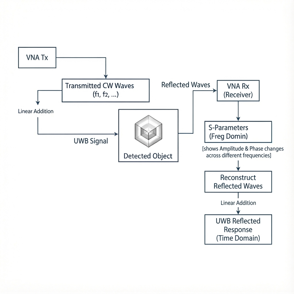
VNA‑based UWB emulation: sweep CW tones, measure S‑parameters, and reconstruct the time‑domain reflected response. - Frequency → time conversion
- Apply windowing (e.g., Hann), zero‑padding if needed, and inverse FFT on complex S‑parameters to obtain the impulse response.
- Build the time axis from the sweep span and frequency resolution to enable TOF reading.
- System delay calibration ((t_0))
- Treat (t_0) as a learnable scalar capturing cables/fixtures; search/optimize it to best align impulses across calibration targets, minimizing range offset on a held‑out set.
- Selected (t_0) is then fixed for subsequent measurements.
- Range estimation (TOF)
- Detect the first significant path in the calibrated impulse response; TOF (\hat{t} = t_\text{peak} - t_0).
- Distance ( \hat{d} = \dfrac{c \cdot \hat{t}}{2} ) (monostatic). Medium corrections can be incorporated if necessary.
- Reference implementation (sketch)
import numpy as np

def freq_to_time(S, f):
    # S: complex spectrum, f: frequencies (Hz), uniform grid
    Sw = S * np.hanning(S.size)  # windowing
    h = np.fft.ifft(np.fft.ifftshift(Sw))  # impulse response
    df = f[1] - f[0]
    T = 1.0 / df
    t = np.linspace(-T/2, T/2, S.size, endpoint=False)
    return t, h

def estimate_range(h, t, t0, c=299792458.0):
    peak_idx = np.argmax(np.abs(h))
    tof = max(0.0, t[peak_idx] - t0)
    return 0.5 * c * tof
Results
| Ground Truth (cm) | Predicted (cm) |
|---|---|
| 5.0 | 5.26 |
| 8.0 | 8.28 |
| 12.0 | 11.44 |
| 16.0 | 15.51 |
| 20.0 | 19.08 |
| 24.0 | 23.86 |
| 28.0 | 27.98 |
| 32.0 | 31.12 |
| 36.0 | 35.99 |
| 40.0 | 38.80 |
| 45.0 | 45.70 |
| 50.0 | 50.38 |
| 55.0 | 55.39 |
| 60.0 | 60.16 |
| 65.0 | 65.72 |
| 70.0 | 70.00 |
| 75.0 | 75.13 |
| 80.0 | 80.41 |
| 85.0 | 84.97 |
| 90.0 | 91.25 |
| 95.0 | 94.80 |
System delay (t_0): 1.52e‑09 s
Best offset (train/test/all): 1.84% / 0.95% / 1.62%
Note: system delay differs by setup and must be re‑calibrated when cables/fixtures change.
Discussion
- Calibrating (t_0) is crucial: uncompensated fixture/cable delays bias TOF linearly, dominating range error.
- VNA‑based excitation offers controllable spectrum and convenient logging; with proper windowing and zero‑padding, the impulse response is sufficiently resolved for short‑range ranging.
- Future work: robust peak picking under multipath, dielectric correction for non‑air media, and joint estimation of (t_0) and distance using probabilistic models.